
The chassis was assembled in Step 1 and the transmissions were built in Part 2, and now it’s time to work on the suspension and get everything mounted to the chassis. This post will bring us right through to the start of the body.
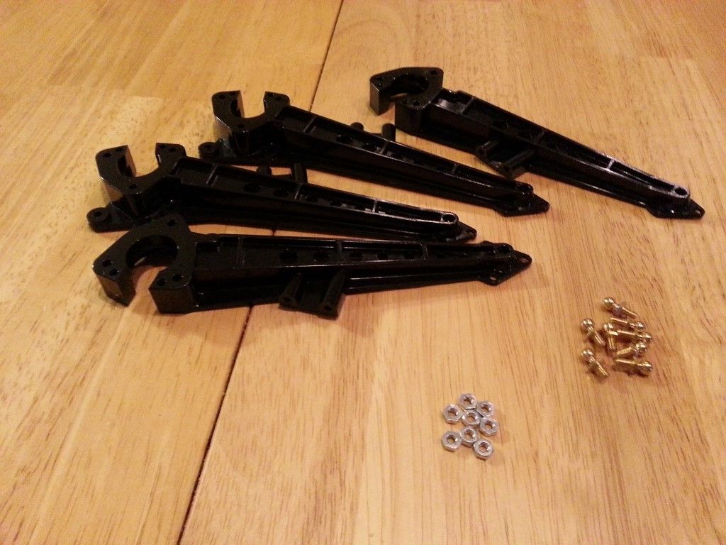
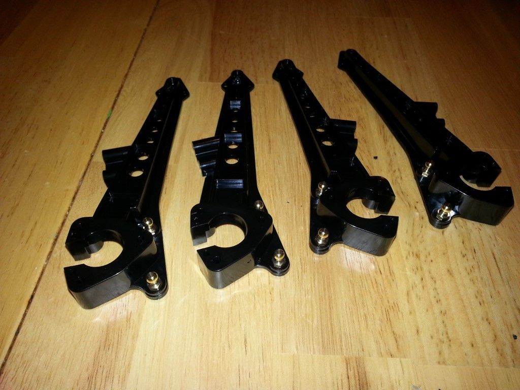
Step 17 – Suspension Arm Assembly
Continue assembling two of everything in this step, two C8 assemblies, and two of C10. This is very straightforward, just screw the BM3 ball connectors into the BC1 nuts. This would be a good place to use a small drop of blue Loctite. I like to use Loctite wherever I have to use plain nuts.
Step 18 – Attaching Suspension Arms
This step can be a little tricky because you have to get the screwdriver to fit around the axle tube in order to fasten the long screws into the C1 parts. Be sure to use a little bit of lube on the round sections of the axle tubes. Use blue Loctite here too on the nuts.
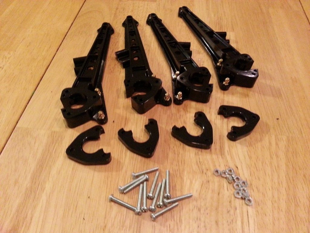
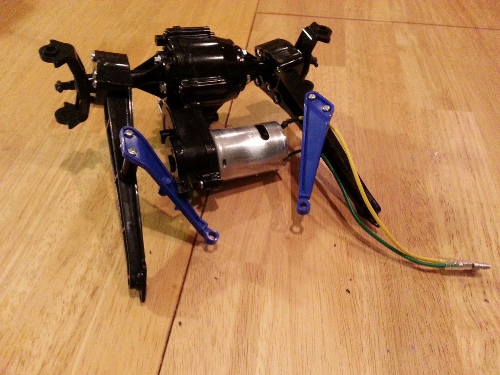
Step 19 – Lateral Arms
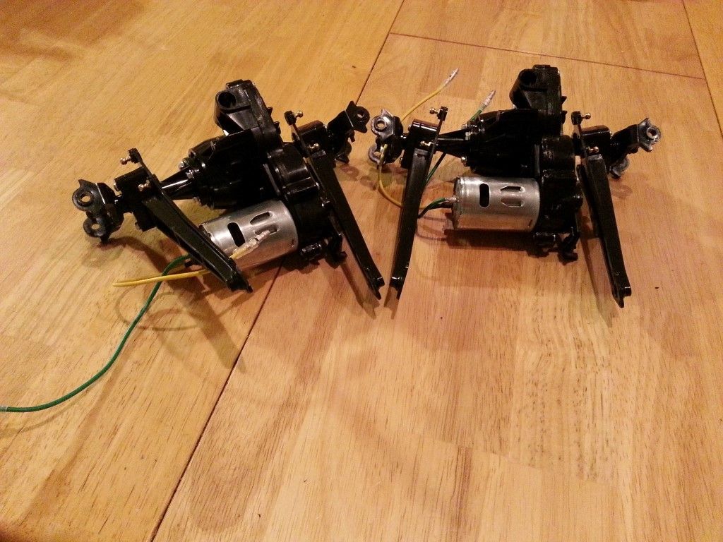
These lateral arms (part F8 and F9) help to keep the gearboxes centered side-to-side. You also need to attach the C6 parts to the suspension arms to capture the arm on the axle tube.
Step 20 – Attaching Axle Stays
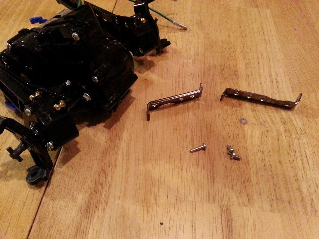
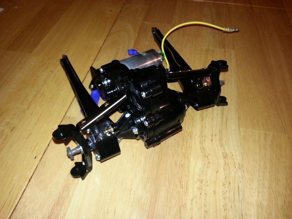
While attaching the steel axle stays, make sure that the short one (BP2) is on the same side of the gearbox as the motor cover, and the long stay (BP3) is on the same side as the motor. They only fit one way, so you can’t get this step wrong. Don’t forget the 3×6 screw that holds the anti-rotation brace to the lateral arm.
Step 21 – Assembling Uprights
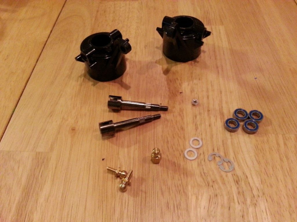
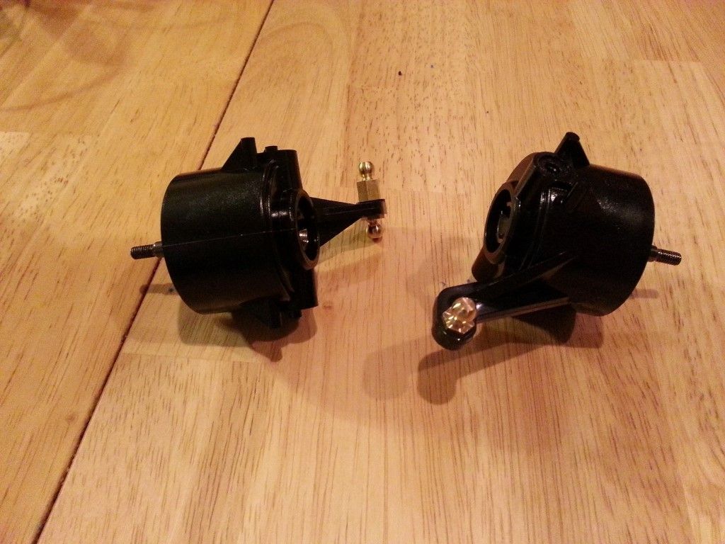
You need to assemble four of these in total, two for the front and two for the rear. Be sure to install ball bearings if you are upgrading now, which is highly recommended. It would be a pain to have to go back after it’s all assembled to add them in. Pay attention to which ball connectors go in which upright. One BH3 goes into D2, and one BH3 and one BH6 ball connector nut go into D1. Also pay attention to the uprights themselves, as D1 and D2 are different. The arm that the ball connectors attach to are closer to the top of the upright.
Step 22 – Assembling Tie-Rods
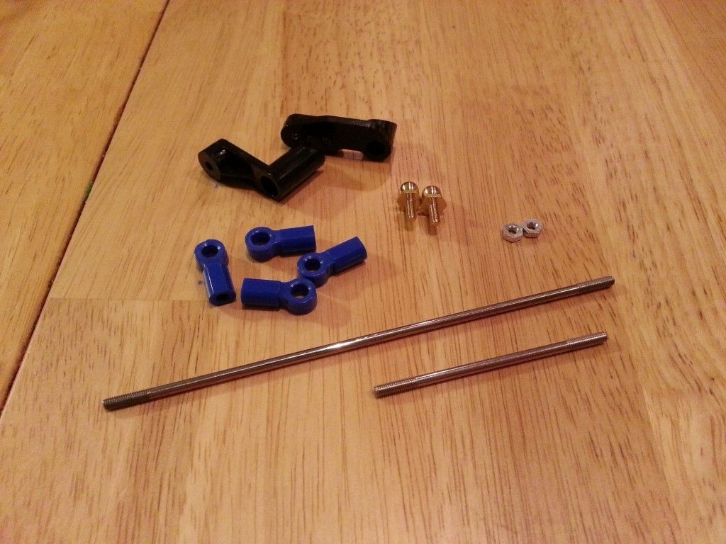
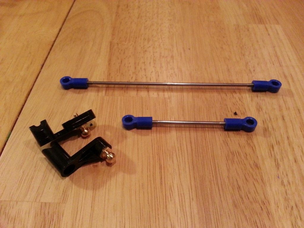
With this step, do yourself a favor and use a caliper if you have one that opens wide enough, or a metric ruler to measure the length of the tie-rods as you attach the ball ends (F7).
Step 23 – Attaching Uprights
Attach the uprights to the axle tubes in this step. Make sure to attach D1 to the motor-side of the transmission, and D2 to the other. The long tie-rod should be closer to the bottom of the gearbox. Put some lube on the shoulder screws (BM4) and the ends of the dogbones.
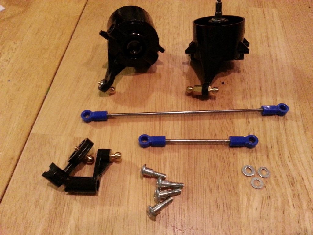
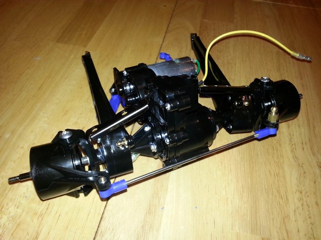
Step 24 – Attaching Steering Arms
It can be a little awkward getting the long screw into the bottom of the steering arms here. Make sure to use a driver with a smaller diameter shaft. The steering arm (B2) should be reversed on the rear gearbox (opposite the motor-side) and it should be on the same side as the motor on the front gearbox. This is really the only difference between the two gearbox units. The more you compress the spring on these steering arms, the less servo-saver action you will have.
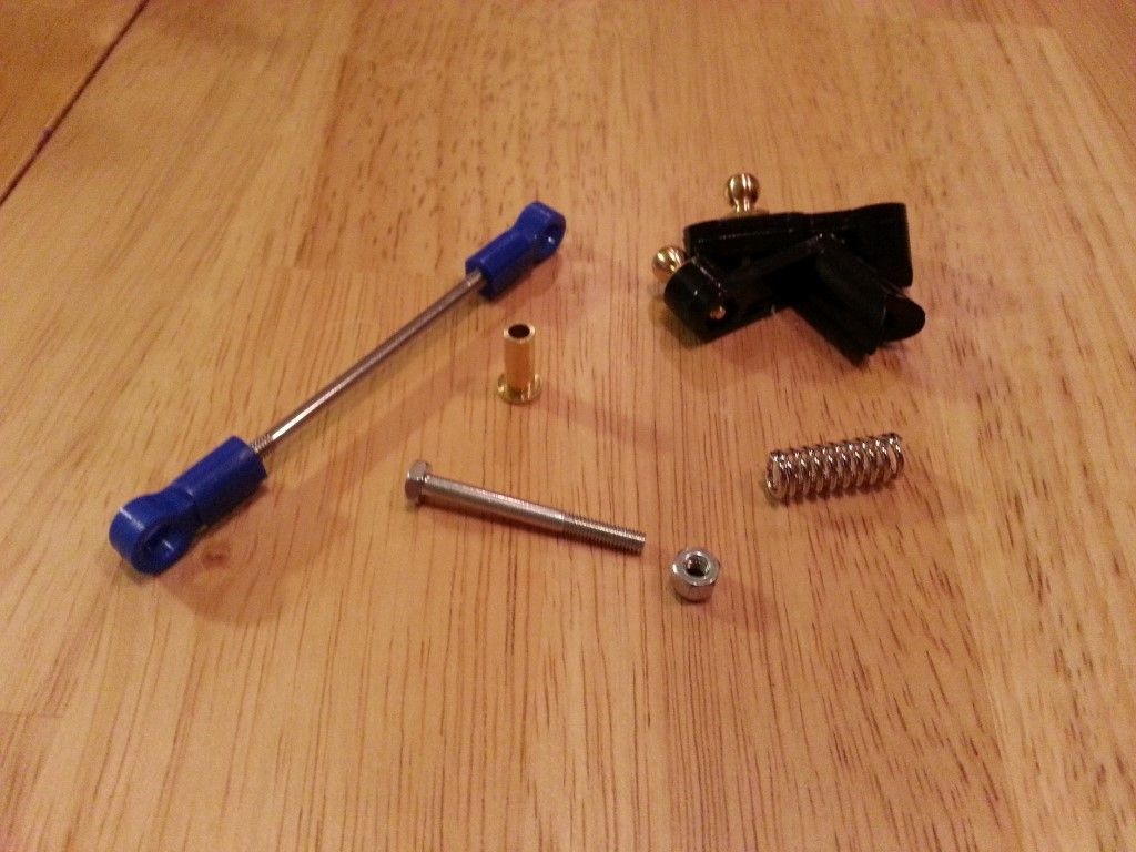
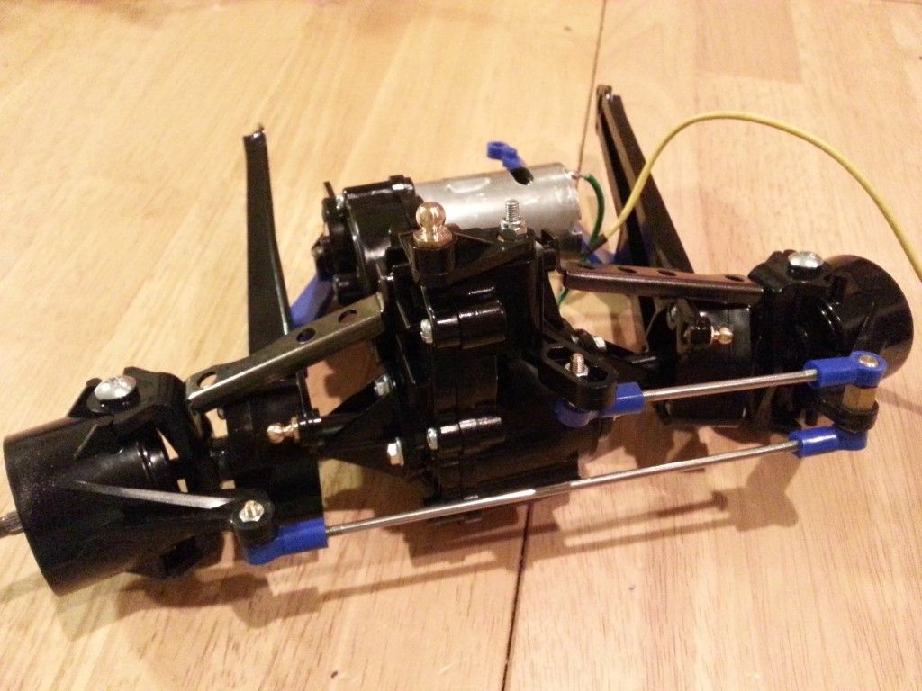
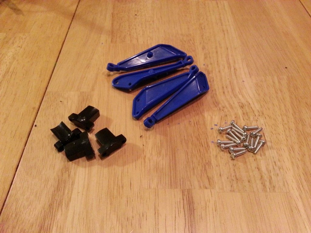
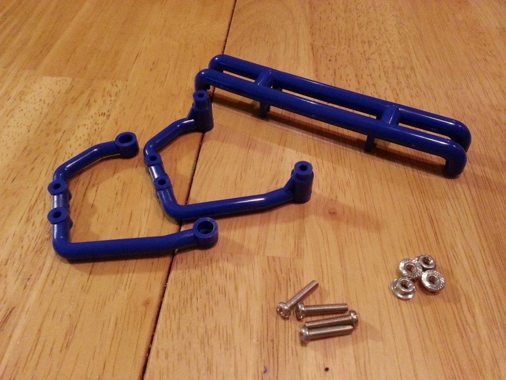
Step 25 – Gearbox Guard Assembly
This is easy stuff. Make two.
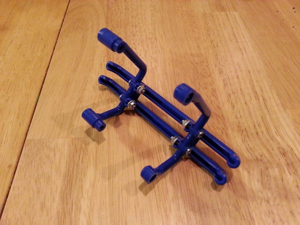
Step 26 – Attaching Gearbox Guard
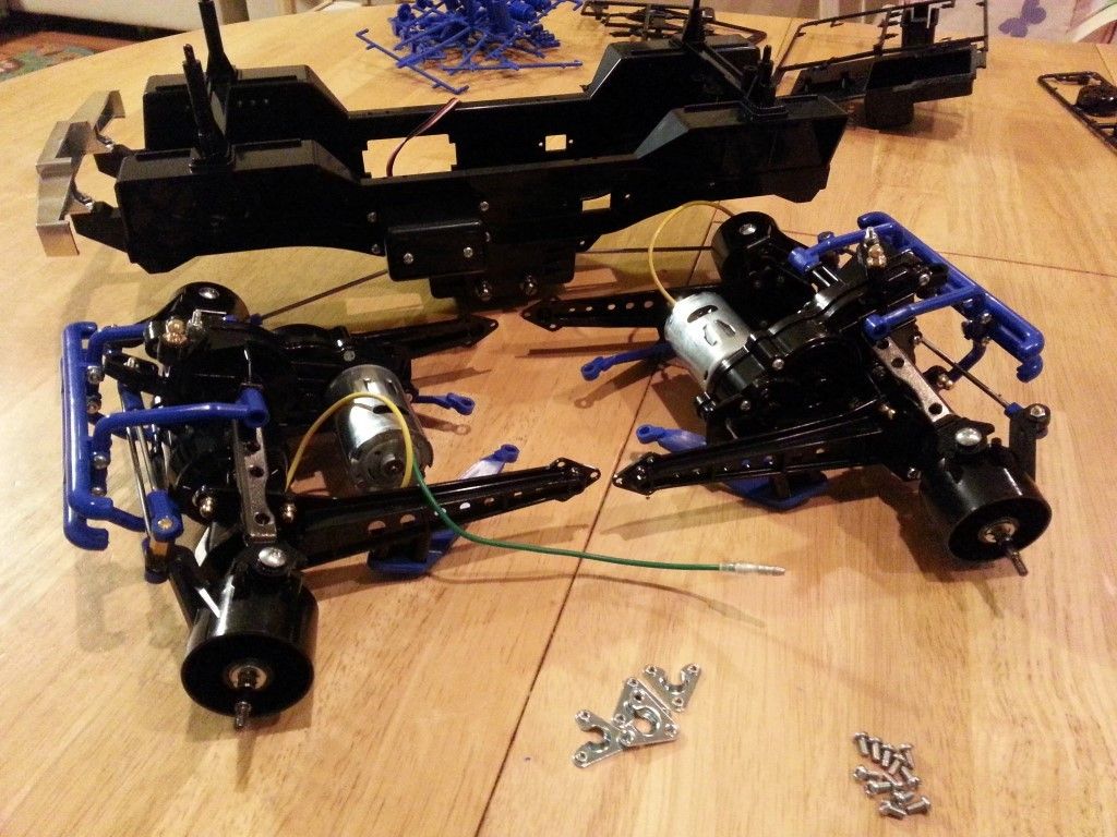
Attach one gearbox guard to each gearbox assembly. They will only fit one way if you assembled them correctly. This is the last step where you will have to make two of everything.
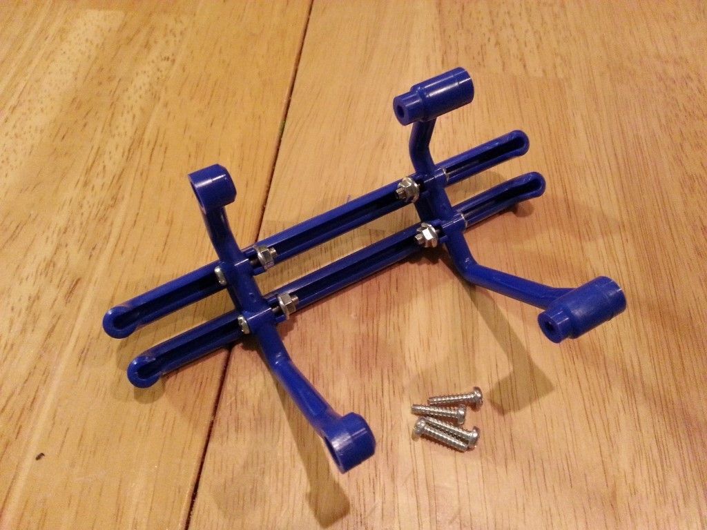
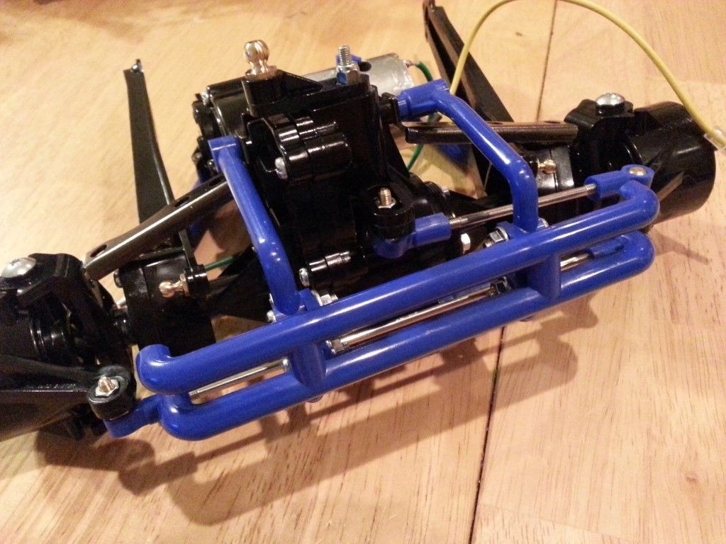
Step 27 – Attaching Gearboxes
This is a pretty big step, and the progress will really start to be apparent when you see the gearboxes hanging off the chassis. Now that you have a front and rear gearbox (you can tell by the steering arms that were attached in step 24), pay attention to which end of the chassis you attach them to. Attach the steering tie-rods that are sticking out of the chassis to the top of each steering arm on the gearboxes. Attach the lateral arms to the ball connectors on the bottom of the chassis using the pinion tool. I used the wrong end of a set of pliers and that worked pretty well too.Also connect the ends of the suspension arms to the large ball connectors on the sides of the chassis. Make sure to lube the ball connectors.

Step 28 – Damper Assembly
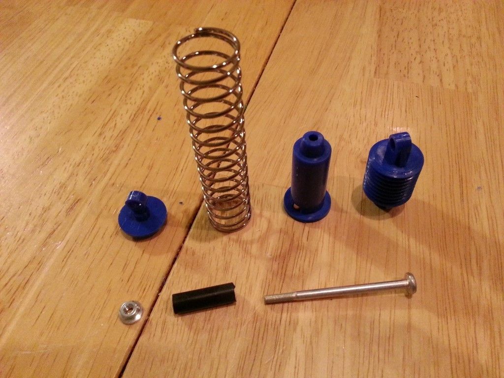
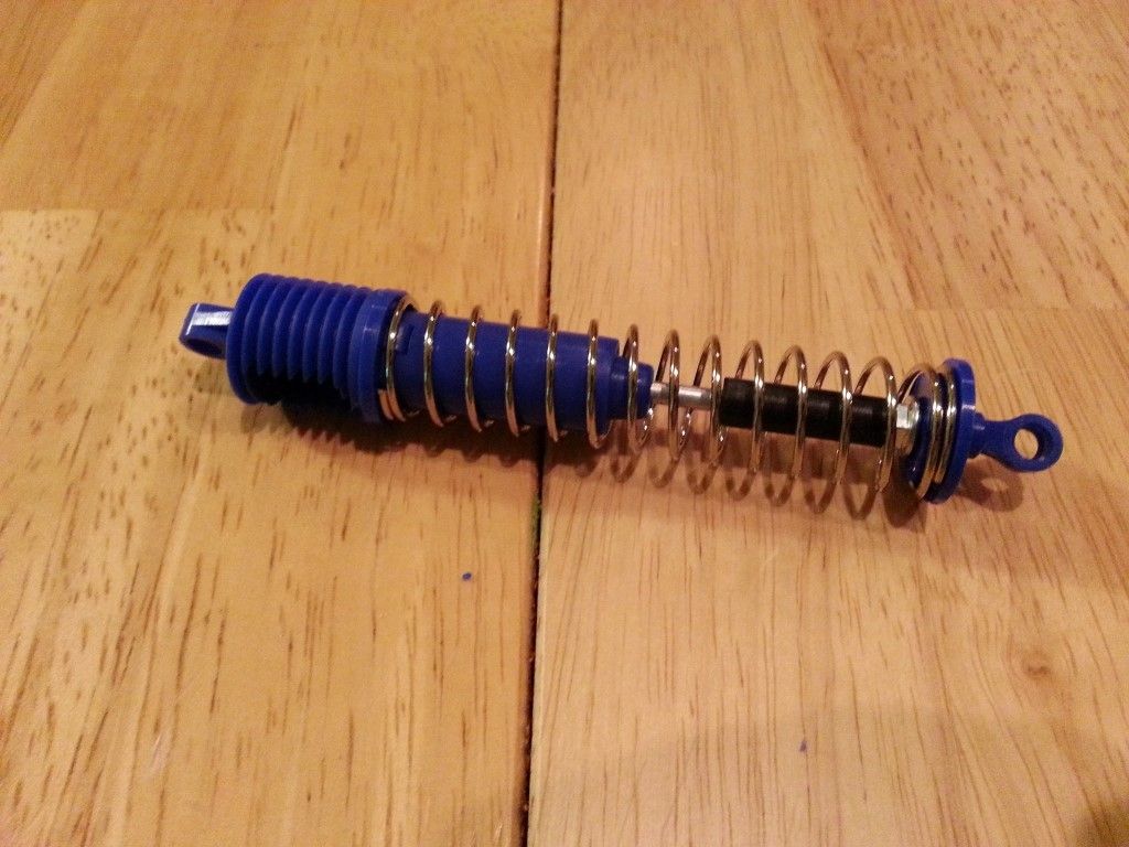
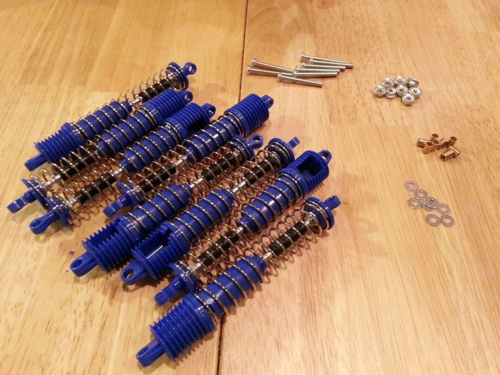
These are simple damper units (not really any damping going on here, just springs). Make 8.
Step 29 – Attaching Dampers
Connect each corner of each gearbox to the chassis using two shocks. It can be a little tricky getting the bottom of the shocks snapped on, but a small needle-nose plier will do the job.
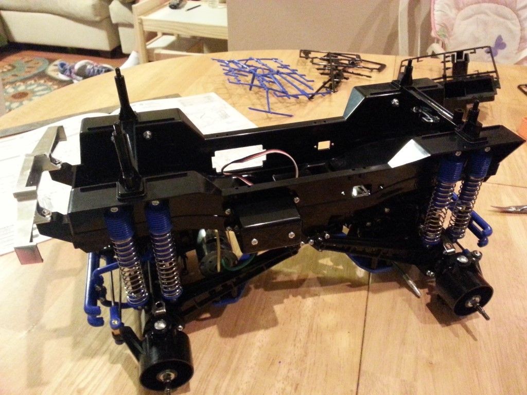
Step 30 – Attaching RC Unit
This is where the ESC is installed. Make note of which wires get connected. For the rear motor, yellow to blue, and green to yellow. For the front motor, yellow to yellow and blue to green. Attach the ESC switch to the chassis.
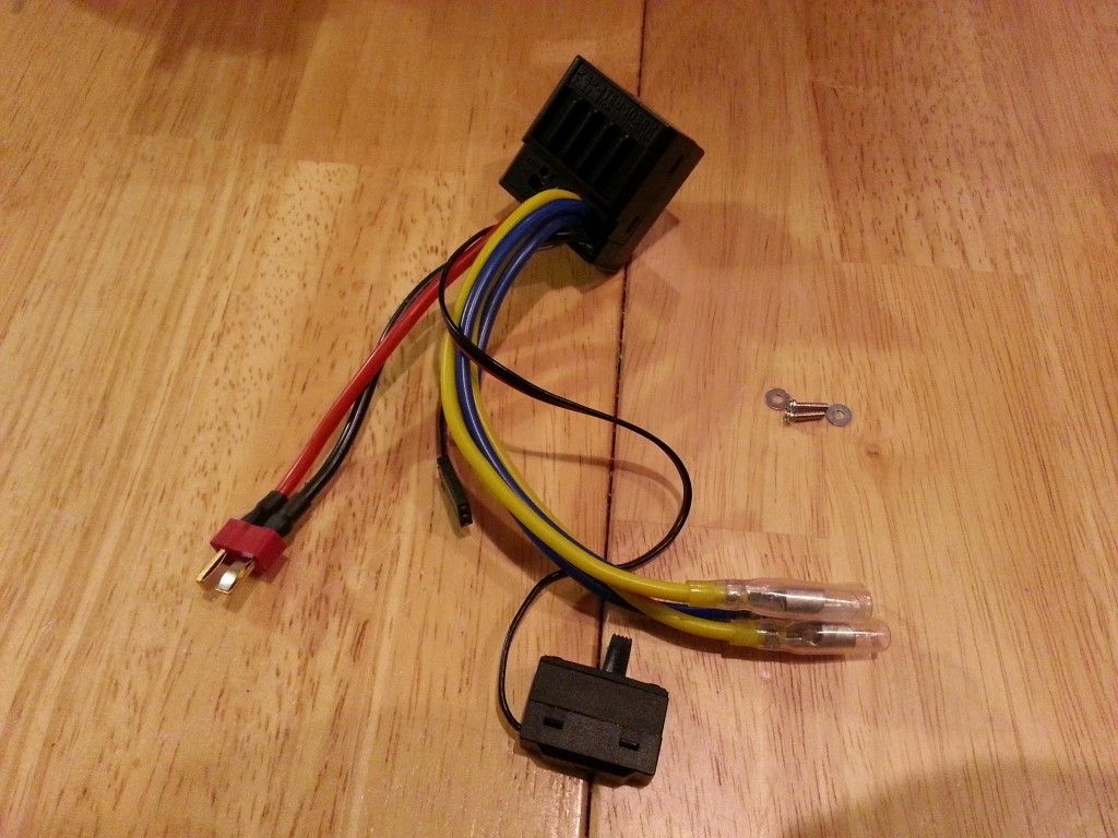
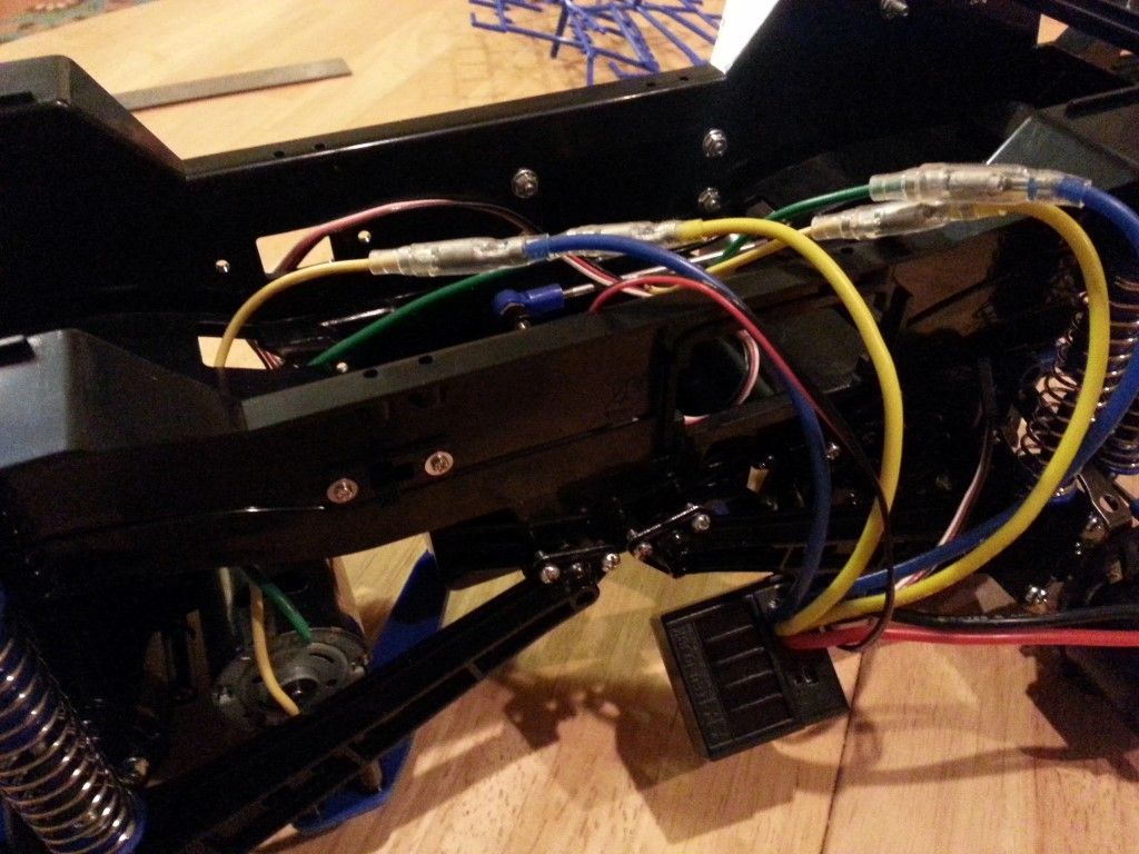
Step 31 – Attaching Mechanism Deck
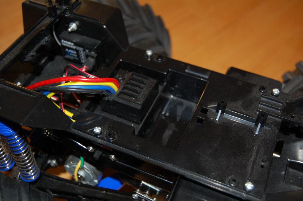
I did some rearranging of the electronics on my truck because I used a 2.4ghz receiver, so I wanted to get the it as close to the antenna mount as possible. The antenna got mounted on the side-wall of the chassis under the body mount brace. The ESC is mounted in the same place as in the manual. I took a lot of extra time here to get all the wires routed comfortably and to make sure the motor and steering servo wires didn’t interfere with the battery.
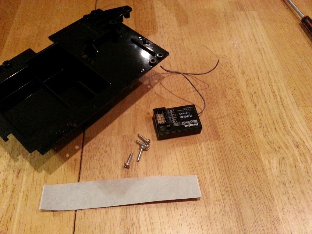
Step 32 – Wheel Assembly
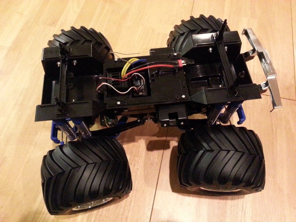
If you opened your kit and didn’t immediately put the tires on the wheels to see how they looked, do that now. And congratulations on your self-control! The tires are directional, and the point that the ribs make in the center of the tires should be pointing forward. Make two left and two right. Use a little cyanoacrylate glue here to attach the tires. I used a few drops of Pro-Line tire glue.

Step 33 – Attaching Wheels
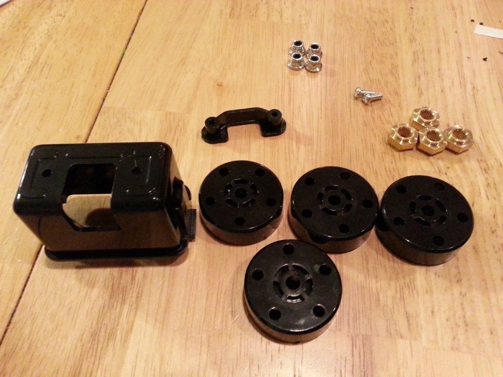
Attach your antenna tube and thread your antenna wire. Build the battery retainer box. Attach all four wheels, making sure that they are pointing forward.
Step 34 – Installing Battery Pack
Nothing too complicated here. Insert battery, attach door.
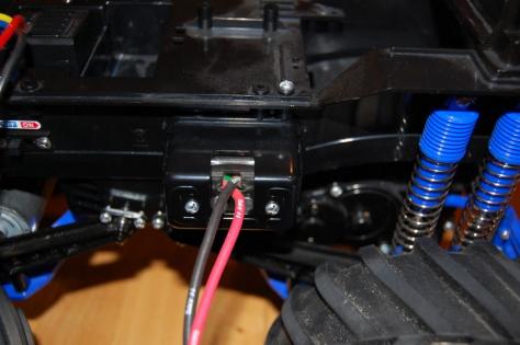

That’s it for this part of the assembly. Next time I’ll paint, decal and assemble the body and finish up this series.

When I did Step 26 attaching the gear box guard, it was very difficult to line up the top screws of the blue guard arms where it attaches to the top of the gear box. I had to bend that metal brace something fierce (the one through which the screw goes into the gearbox). When I got the screw in, my gears got extremely tight, so tight I could no longer rotate the axle with my hand. When I took the screw out, the gears freed up.
So now, I cannot screw in the upper arms of the blue guard, without the gears getting too tight. What is going on?…
I would make sure that you’re using the correct screw to hold on the bumper and brace. It sounds like the screw was holding up the gear somehow. Are you sure you were using the correct steel brace in that location? They should line up really nicely unless they were manufactured wrong.