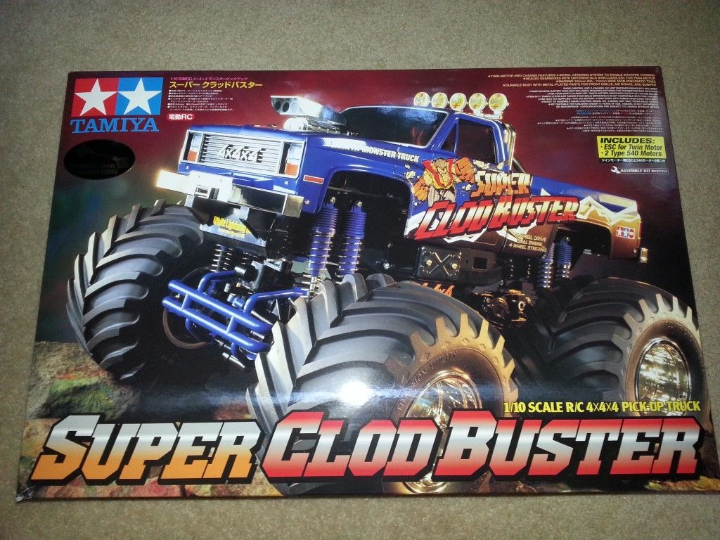
This is going to be the first of a series of posts documenting my build of the Tamiya Super Clodbuster. I bought my first Clod used back in the early nineties, so this is my first official right-out-of-the-box build of a stock Clodbuster.
I’m going to document this build step-by-step, according to the instructions. I’ll try to have one photo showing the parts needed to complete the step, and one photo of the completed step.
Step 1 – Checking R/C Equipment
The first thing the manual asks you to do is test your electronics, which is sound advice. It would be bad to get everything installed and find out something isn’t working. I replaced the plug on the included speed control (a Tamiya TEU-103BK) with a Deans Ultra Plug. I plugged everything in and matched the new Futaba R2004GF receiver with my transmitter. After setting up the ESC according to the instructions, everything was working fine. This step also allows you to set your servo to neutral (right in the middle) before attaching the servo horn in Step 2.
Step 2 – Attaching Servo Horn
Next up is assembling the servo horn and attaching it and the servo mounts to the steering servo. Here I am using a Hitec HS-615MG servo. It’s got 132.0 oz-in of torque and a speed of 0.17 sec/60°, both at 6.0v, with metal gears and dual ball bearings. It should be enough to get me going, but I suspect I might have to upgrade it later because these are some big wheels and tires and the steering on this truck is notoriously poor, especially in the front.
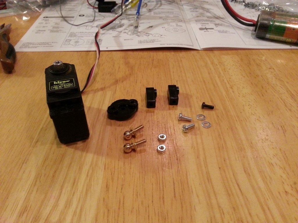
Use the servo horn that matches your servo. Tamiya includes two of them in the kit. Attach the servo horn with the brass ball links perpendicular to the length of the servo (up and down with the servo laying on its side).
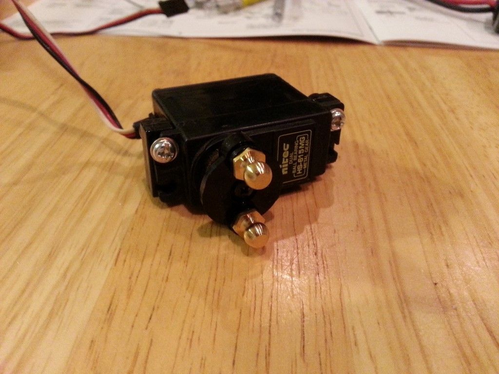
Step 3 – Attaching Steering Rods
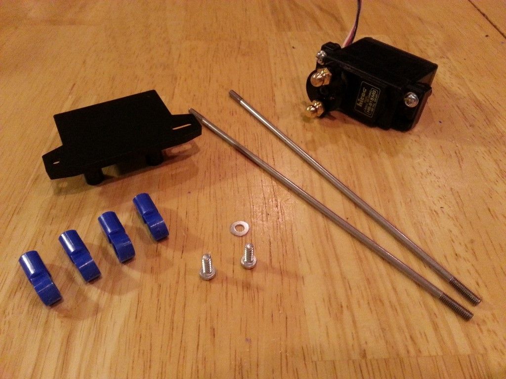
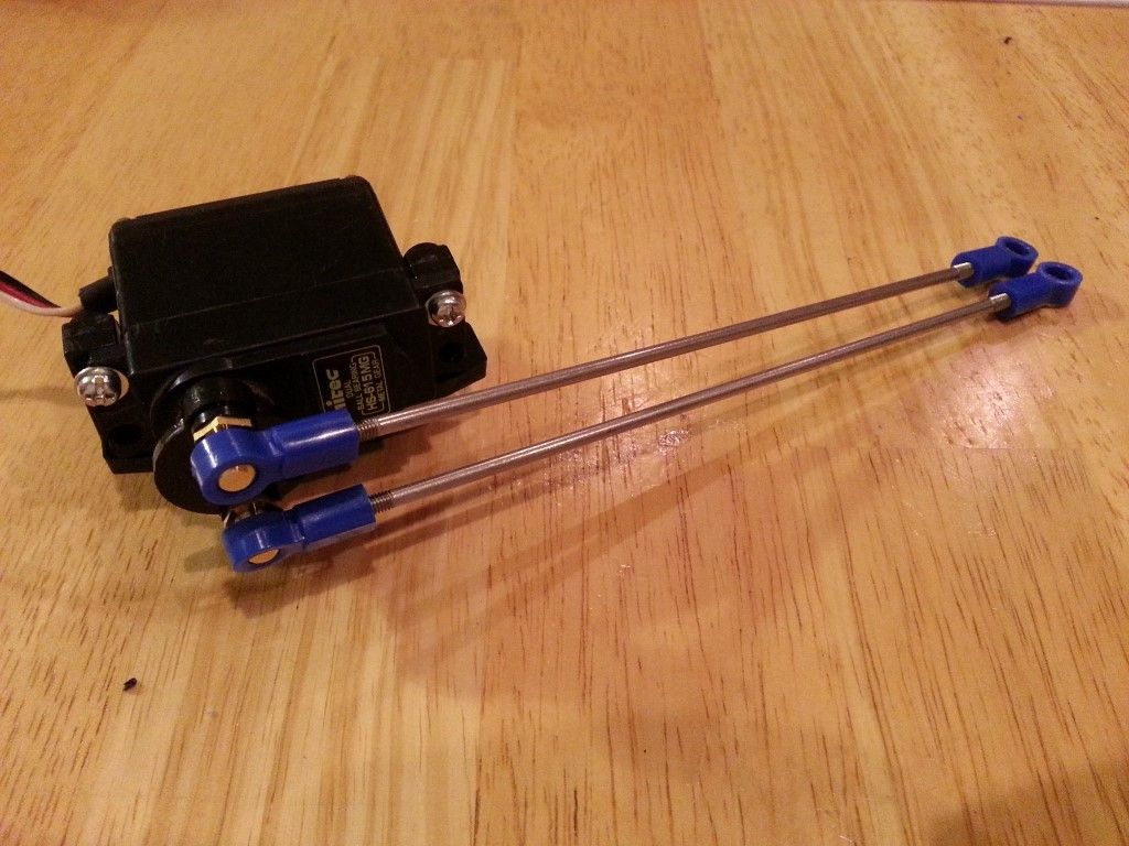
Step 3 involves attaching the steering servo to the servo mount, and assembling the long steering links that attach the servo to the servo savers on the gearboxes. Pay close attention to the length of the steering links here and use a ruler or a caliper to make sure they are set to 126mm between the ends of the plastic rod ends.
Step 4 – Chassis Assembly
Now it’s time to start working on the chassis. Here we need to attach the reinforcing plates that support the suspension arm mounts, and the ball links.
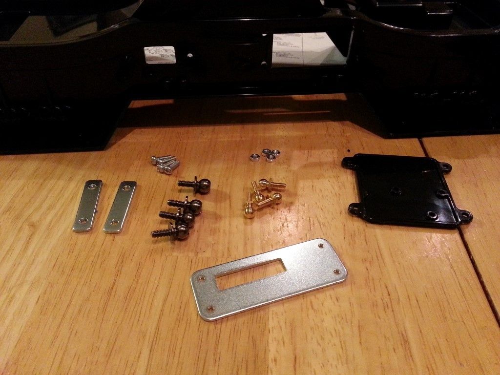
In the large square hole in the bottom of the chassis, there are mold tabs that need to be removed with a hobby knife or file. Here’s a shot after the cleanup.
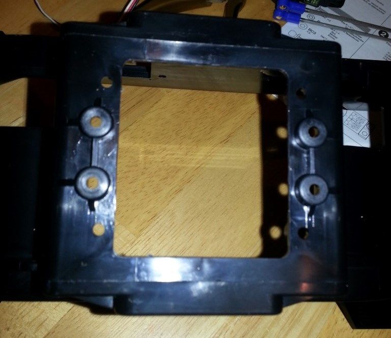
Make note of the two different types of ball studs being used. The larger black ones go on the sides, the smaller brass ones on the bottom. The large steel plate is directional and the slot should be on the right side of the chassis, closest to the rear. There are markings on the chassis bottom marking the front (F) and rear (R) of the chassis. When you attach the square plastic plate, the three small holes should be closest to the rear of the chassis.
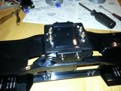
Step 5 – Attaching Front Body Mount
Moving up to the front of the chassis, it’s time to install the chrome front bumper and the front body mounts and body mount support. Here is also where we start applying stickers. The White Lightning and 4x4x4 stickers go on here.
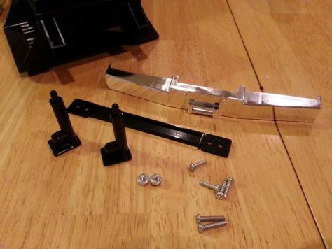
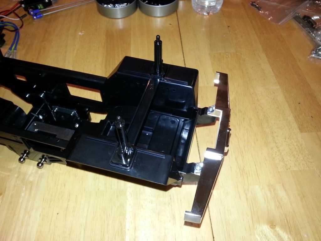
Starting to look something like a truck!
Step 6 – Attaching Rear Body Mount
This step is pretty much the same as step 5, minus the bumper. Don’t forget the stickers!
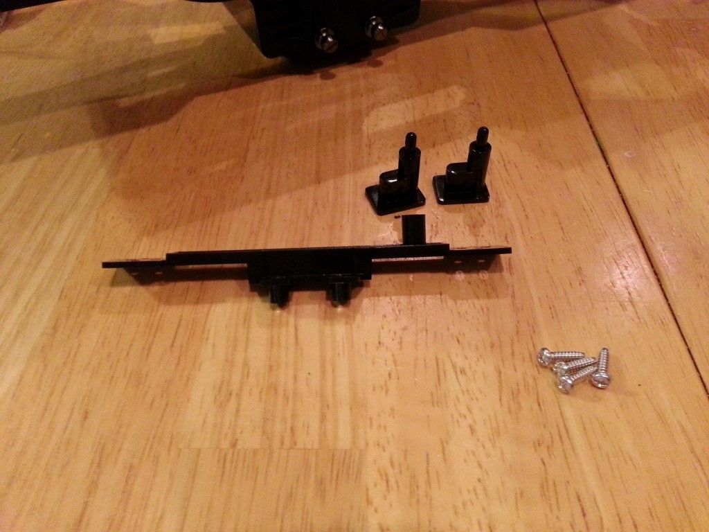
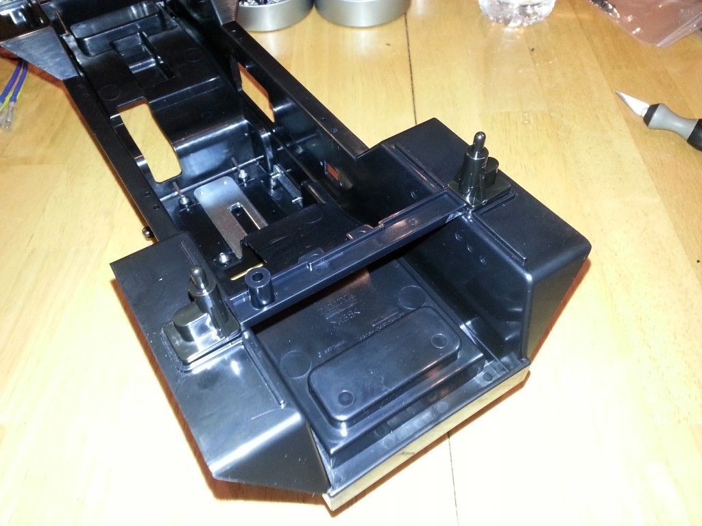
Step 7 – Attaching Steering Servo
Take the completed steering servo assembly from step 3 and install it into the chassis. Pay attention to the orientation of the servo links, bottom one toward the back, top one toward the front.
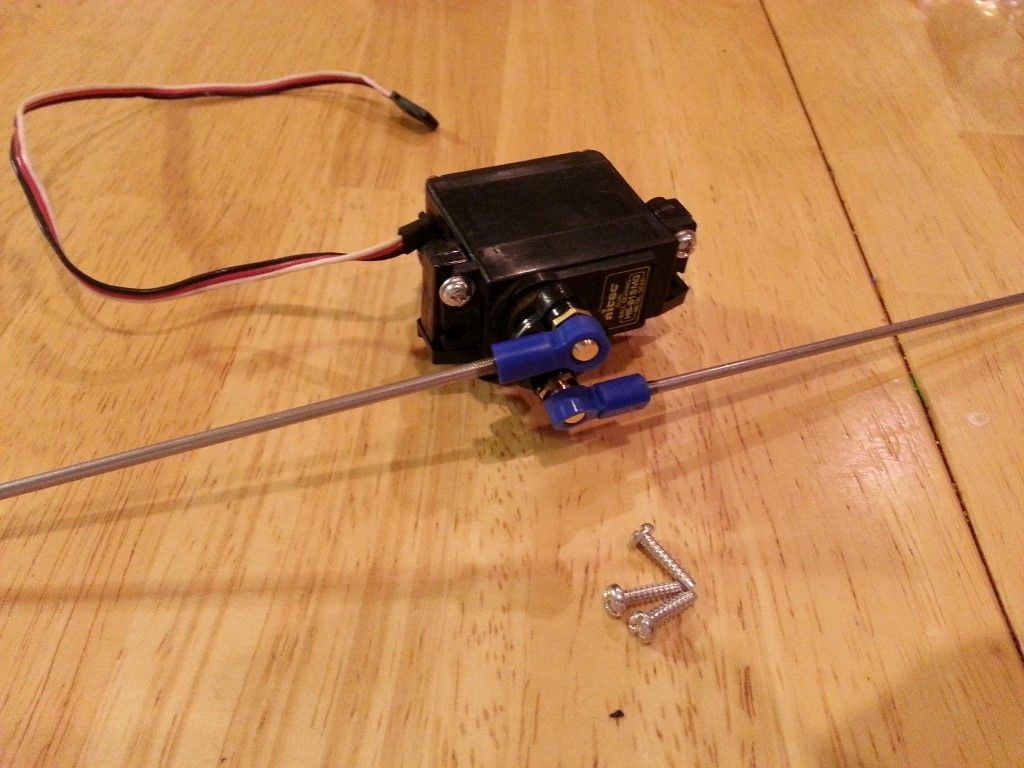
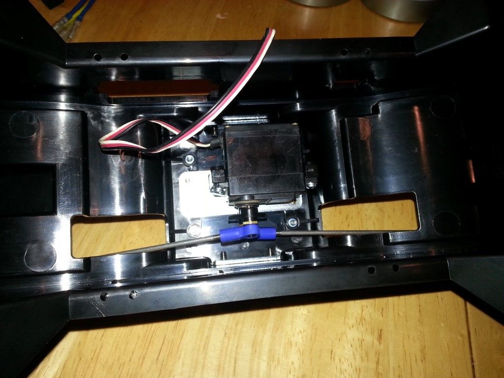
Step 8 – Attaching Battery Holder
Here is where we install the left battery holder. The right one will go on later after the battery goes in.
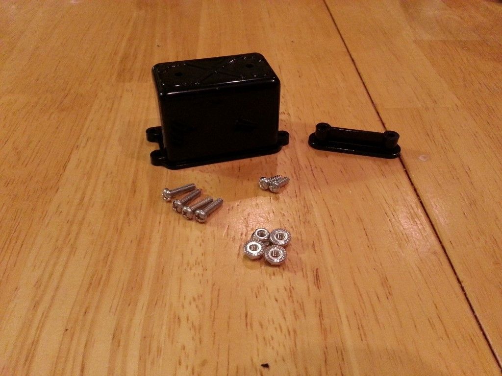
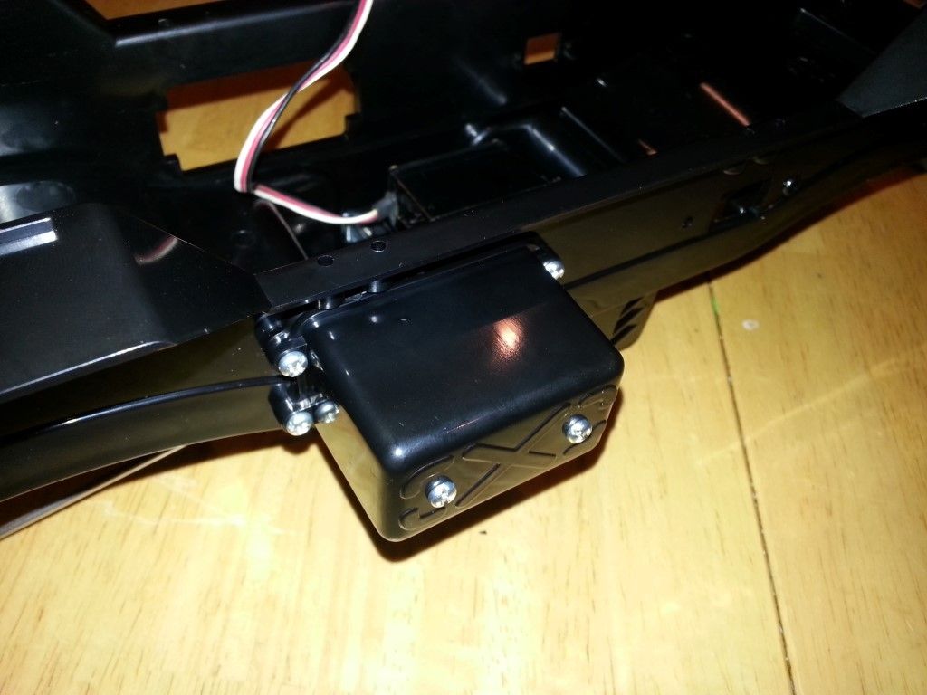
That’s going to do it for this installment of the Super Clodbuster build. Next time, we’ll say goodbye to the chassis until step 27. We’ve got 18 steps worth of transmissions to build, which are easily, the toughest part of this kit.

Where do i get the servo horn?
The steering servo horns are on the H part tree, parts H3 and H4. You’ll have to choose the right one for your servo.
Excellent guide. One note, the standard servo horns in the kit (plastic disk that fits on the servo) are 23t and 25 tooth in Tamiya kits. Most Hitec servos are 24t and wont fit correctly, which means you must buy/use a 24t horn.
I found that out the hard way! The Tamiya servo horn quickly stripped out and I had to replace it with one that came with the Hitec 615MG servo.